

ElectroCorner
Energize Yourself
Circuit Analysis
There are a number of tools you can use for very small electrical circuits. For example, given a small electrical circuit you can do any or all of the following.
-
Look for resistor combinations - either series or parallel,
-
Look for sourcesthat you can find a Thevinin or Norton equivalent for,
-
Look for embedded voltage dividers,
-
Hope that all of the above will lead to a very simple circuit that you can analyze.
But - - - what happens when you do all of that and you still can't figure out what goes on?
-
You need some general method that you know will get you to a result.
In other words, what you may need is a method that has a high probability of success - one that is almost guaranteed to work for a large variety of circuits. There are two general methods you might try in that situation:
-
The method of node voltages,
-
The loop equation method.
In this lesson you will begin to learn some general methods for analysis of electrical circuits. When you learn those analysis methods you will have increased the number of tools in you analysis toolbox. We ask you to be thoughtful as you do that. If your regular toolbox is empty and someone gives you a hammer, then pretty soon everything will start to look like a nail. Not only do you have to learn the tools for analysis, you also have to learn when you need to use them, and how to choose from the tools in your toolbox.
Node Voltage Equations
We are going to start with the method of Node Voltages. The name of the method tells you exactly what you are going to do.
-
The method of Node Voltages starts with writing the KCL equations for the nodes in a circuit. Those equations are written in terms of node voltages (even though you are writing the Current Law, the variables are voltages!) thus the name!
That's a little simplified, but that is the essence of the method. We'll start with a simple circuit, and we will try to discover what you have to do. Here's a very simple circuit. It is a voltage divider. We notice some very simple facts about this circuit.

-
There are two nodes in this circuit. One is marked with a red dot, the other is marked with an green dot.
-
There is a difference between the two nodes. If we know Vs - the source voltage - then we know the voltage at the node marked with an green dot.
-
We don't know the voltage at the node marked with a red dot unless we do some analysis.
Now, what we are really saying about this circuit is the following.
-
Since there is only one node where we do not know the voltage, when we write the equations for this circuit, we really only need one equation.
-
There's one unknown and there's going to be one equation.
-
The equation we need to write is KCL at the node with the unknown voltage
Now, we will write the equation at the node with the unknown voltage.
-
We need to define a symbol for the unknown voltage. We'll call it Vx.
-
Then we write KCL at the node where Vx appears.
-
Finally, we solve whatever equation results from writing KCL.

Now, we will write the equation at the node with the unknown voltage.
-
To write KCL we need to define two currents for this case. They are shown below.

-
Then KCL is written as:
-
Ia + Ib = 0 since both currents are leaving the node.
-
-
We need to get expressions for Ia and Ib. The expressions we need are:
-
Ia = (Vx - Vs)/Ra
-
Ib = (Vx - 0)/Rb
-
In both cases the voltage across the resistor causing the current to flow in the indicated direction is:
Voltage at the node - Voltage at other resistor end.
-
Note that one end of Rb is connected to ground, so a zero appears in that expression.
-
It is important to be sure you understand how each current is calculated, and the exact expression for the current. The current through a resistor, R, connected to a node is:
(Voltage at the node - Voltage at other resistor end)/R
-
Then, since:
-
Ia = (Vx - Vs)/Ra and
-
Ib = (Vx - 0)/Rb
-
-
We can write the complete KCL equation.
-
KCL gives us: Ia + Ib = 0.
-
-
So, we have:
-
(Vx - Vs)/Ra + (Vx - 0)/Rb = 0
-
Now, remember the algorithm for using node voltages.
-
Define a symbol for the unknown voltage. We've done that.
-
Write KCL at the node where Vx appears. Done that also.
-
Solve whatever equation results from writing KCL. We need to do that.
We need to learn how you can solve these kinds of equations. It's not hard to solve the equation we have:
(Vx - Vs)/Ra + (Vx - 0)/Rb = 0
The result is:
Vx = Vs*Rb/(Ra + Rb)
Actually, this circuit was pretty easy.

-
This circuit has one unknown node voltage.
-
We wrote one KCL equation.
-
We had one equation with one unknown.
Now, we'll look at a more complicated circuit.
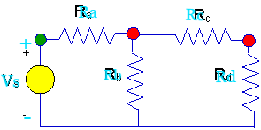
Here is a more complicated circuit. This ladder circuit is more complex for one simple reason.
-
This circuit has two unknown node voltages.
-
The nodes with unknown voltages are marked with red dots.
-
Once again, we have a node where the voltage is known, and it is marked with an green dot.
-
We use the same solution algorithm as before.
-
Define symbols for the unknown voltages. We'll use Vx and Vy.
-
Then we write KCL at the nodes where Vx and Vy appear.
-
Finally, we solve whatever equations result from writing KCL.
For the first step:
-
Define symbols for the unknown voltage - Vx and Vy. They are shown on the diagram below.
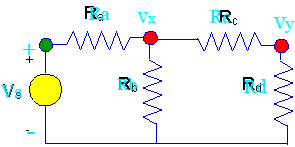
Vx and Vy are shown at the respective nodes. Notice again that the voltage and the node with the orange dot is already know to beVs volts when measured with respect to ground.
For the second step:
-
Write KCL at the nodes where Vxand Vyappear.
Again, currents need to be defined. Let's work on node x first. Define currents as in the figure below, and write KCL.

Ia+ Ib + Ic = 0.
-
Then express each current in terms of the node voltages.
-
Ia = (Vx - Vs)/Ra
-
Ib = (Vx - Vs)/Ra
-
Ic = (Vx - Vs)/Ra
-
So, if we put these current expressions into the KCL equation, we get:
(Vx - Vs)/Ra + (Vx - Vs)/Ra + (Vx - Vs)/Ra = 0
Now, we need to solve this equation. This is one equation, but it has two unknowns, Vx and Vy. We need a second equation, and clearly it is obtained by writing KCL at node y. Writing KCL at node y we get:
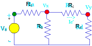
Ic' + Id = 0
-
We use Ic' because it is not the same as Ic. Actually Ic' = - Ic.
-
Still, using these definitions, we get:
-
Ic' = (Vy - Vx)/Rc
-
Id =(Vy - 0)/Rd
-
Combining the expressions for the terms in KCL at node y, we have:
(Vy - Vx)/Rc + (Vy - 0)/Rd = 0
And, the equation we had from node x is:
(Vx - Vs)/Ra + (Vx - 0)/Rb + (Vx - Vy)/Rc = 0
Now, we're going to write out both equations and combine Vx and Vy terms. Here's the result of rearranging the equations that way.
Vx(1/Ra+ 1/Rb + 1/Rc) -Vy/Rc = Vs/Ra
Vy(1/Rc+ 1/Rd) - Vx/Rc = 0
These are close to what we want. We are going to rearrange these equations to show the coefficients of Vx and Vy better next.
Vx(1/Ra+ 1/Rb + 1/Rc) -Vy/Rc = Vs/Ra
-Vx/Rc+ Vy(1/Rc+ 1/Rd) = 0
There are several things to note here, even though we only have a set of equations to solve, and we haven't solved those equations yet.. First, the equations can be easily obtained from the circuit diagram. We'll work on that in a while, but you may already have noticed that there is a kind of symmetry to the equations, and there are clear relationships between the nodes the resistors are connected to, and how those resistance values enter into the equations.
You may also have noted that the equations that result are simultaneous linear equations. Basically, you have two unknown node voltages, and the equations you write result in two equations in those two unknown node voltages. You know everything else in the equations, including resistance and source voltage values.
Finally, you may already know several algorithms for solving simultaneous linear equations.
Solving The Node Voltage Equations
Given these two equations:
Vx(1/Ra+ 1/Rb + 1/Rc) -Vy/Rc = Vs/Ra
-Vx/Rc+ Vy(1/Rc+ 1/Rd) = 0
One possible approach to solving these equations is back substitution. The method of back substitution is fairly simple in concept although you will need to be careful with details in the execution of the algorithm. Here is the process.
-
Solve an equation for one of the unknowns.
-
You can pick any equation you want, but pick one.
-
-
You will get an expression for the chosen unknown that involves the rest of the unknowns and the circuit parameters.
-
Then, plug your expression for the chosen unknown into all of the other equations wherever the chosen unknown appears.
-
Vx(1/Ra+ 1/Rb + 1/Rc) -Vy/Rc = Vs/Ra
-
-Vx/Rc+ Vy(1/Rc+ 1/Rd) = 0
-
-
In this set of equations, we are going to solve the second (lower) equation for Vx. Doing that, we get:
-
Vx = VyRc(1/Rc+ 1/Rd)
-
-
Now, we can take this expression for Vx and use it in the first (top) equation. Doing that we get:
-
VyRc(1/Rc+ 1/Rd)*(1/Ra+ 1/Rb + 1/Rc) - Vy/Rc = Vs/Ra
-
-
This equation can be solved easily for Vy. Collect all the terms on the left hand side and solve.
-
Vy = Vs/[Ra/Rc(1/Rc+ 1/Rd)*(1/Ra+ 1/Rb + 1/Rc)-1/Rc]
-
This can be simplified even further. You can simplify this further, and we'll leave that to you.
Given a set of equations arising from applying the node voltage method, there are several solution options. So far we can see the following.
-
With one unknown node voltage, one equation results and it can be solved easily.
-
With two unknown node voltages, two equations result, and they can be solved with the method of back substitution.
-
With three unknown node voltages, three equations would result. We could use back substitution to eliminate one of the variables, getting two equations, then use back substitution again to get to one variable and solve. It looks and sounds messy, but we could do it.
Or, would it be better to look at more general methods? There are other methods we could conceivably use. Let's think about the kind of equations we have to deal with.
-
As long as we have linear resistors - and no diodes, transistors, etc. - we will always get a set of simultaneous linear equations when we write the node equations.
-
Back substitution is a well-known way of solving sets of linear equations, but other methods based on determinants and matrices are widely used.
-
Many mathematical analysis packages - like Mathcad and Matlab, for example - have built-in routines for solving sets of simultaneous linear equations. If we want to use methods based on determinants and matrices, and especiallly if we want to use the packages available, we will need to be able to represent our node equations in a way that is different.
-
We need to be able to represent our equations in a vector-matrix format.
Let's re-visit the equations for the ladder network. Here they are again.
-
Vx(1/Ra+ 1/Rb + 1/Rc) -Vy/Rc = Vs/Ra
-
-Vx/Rc+ Vy(1/Rc+ 1/Rd) = 0
A vector-matrix representation that contains the same information is given below.

The vector-matrix formulation has several important characteristics.
-
The information about the circuit connections are contained in a matrix that has numerous reciprocal resistance values. Actually, they are conductances, and this matrix is called the conductance matrix.
-
The unknown node voltages are represented as components in a voltage vector.
-
The voltage source gets embedded in a source vector on the right hand side of the vector-matrix equation for the circuit.
The vector-matrix formulation has the general form:
G * v = I
-
The matrix, G, is the conductance matrix. It has units of ohms-1.
-
The vector, v, is the node voltage vector. It has units of volts.
-
The vector, I, is the source vector. It has units of current.
To solve for the voltage vector is simple in principle. One only needs the inverse of the conductance matrix.
v = G-1*I
Getting it is another story. How many ways do you know to take the inverse of a matrix? How do you invert a matrix? Let us count the ways.
-
The inverse of a matrix, G, is given by:
-
Adj(G)T/|G| so, you can compute an inverse by hand.
-
-
Mathcad and Matlab have matrix inversion functions. Use them.
Well, that's two or three ways. Here is the inverse and the circuit.

We wanted to show you this first because we wanted to build a case that it may not be a good idea to compute this inverse symbolically by hand. This is not a large circuit, and the analytic inverse looks fairly horrendous.
-
Even a circuit as simple as this points to the fact that numerical solutions to circuits are very important. In turn, that implies the you need to be familiar with numerical ways to solve the kinds of equations that come out of linear circuits. That means you need to understand the algorithms and you need to be able to use those algorithms in various incarnations especially as they appear in analysis applications like Mathcad and Matlab.
Before we do, there are some things we need to point out about the conductance matrix.
-
Ra, Rb and Rc are all attached to the first node, where Vx appears.
-
In the conductance matrix, the reciprocals of all those resistances are added together to give element (1,1).
-
-
Similarly, Rc and Rd are attached to the second node, and their reciprocals are added to give element (2,2) in the conductance matrix.
-
Finally, note that Rc is shared between the two nodes, and the negative reciprocal of Rc appears in elements (1,2) and (2,1) in the conductance matrix.
It should be clear that there's a pretty slick way to fill in a conductance matrix in the rules above. Review that material to be sure you understand it. You can always write down a conductance matrix from a circuit by following these two rules.
-
If you have a resistance between two nodes, node m and node n,
-
Then that resistance contributes a term that is the nevative reciprocal of the resistance to the (n,m) entry in the conductance matrix, and to the (m,n) entry in the conductance matrix.
-
All such contributions are added together.
-
-
If you have a resistance attached to node n,
-
Then that resistance makes a positive contrbution to the (n,n) entry.
-
That's it. At this point, you are invited to check those results for this circuit.